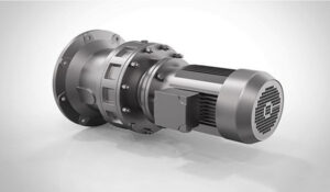
Operation Principle and Structure Characteristics of Worm Gear Reducer

Worm gear reducers are usually used in low-speed and high-torque transmission equipment. Its principle is to use electric motors, internal combustion engines, motors or other high-speed running power to mesh with gears with fewer teeth on the input shaft of the worm gear reducer. Gears, in order to achieve the purpose of deceleration; the ratio of the number of teeth of the large and small gears is the transmission ratio.
Worm gear reducer is an independent component composed of gear transmission, worm transmission, and gear-worm transmission enclosed in a rigid shell. It is often used as a reduction transmission device between the original moving part and the working machine. It plays the role of matching the speed and transmitting torque between the prime mover and the working machine or the actuator. It is widely used in modern machinery.
1. The box structure of the worm gear reducer is integral, with beautiful appearance and good rigidity. The cabinet type has basic type (the cabinet is a vertical or horizontal structure with a foot plate) and a universal type (the cabinet is a cuboid, with fixed screw holes on multiple sides, without a foot plate or additional foot plates, etc. Various structure types)
2. The input shaft connection mode of worm gear reducer has two basic types (single input shaft and double input shaft), with motor flange; the output shaft structure has basic type (single output shaft, double output shaft) and hollow output shaft Two kinds.
3. The worm gear reducer output and input shaft position direction has the input shaft down and up; the output axis is up and down; the input axis is up and down.
4. Two or three reducers can be used to form a multi-stage reducer to obtain a great transmission ratio.
